

Next: MC-8 The Physical Pendulum
Up: PHYS 201/202 and 207/208
Previous: M-6 Uniform Circular Motion
OBJECTIVES:
*.3in
To measure how the period of a simple pendulum depends on
amplitude.
To measure how the pendulum period depends on length if the amplitude
is small enough that the variation with amplitude is negligible.
To measure the acceleration of gravity.
VIRTUAL PRE-LAB EXPERIMENT:
*.3in
For students wishing to try this experiment out on-line. There is
an available JAVA pendulum applet. Simply click on the Launch Virtual Pendulum
button below.
Start the pendulum swinging and
then let it swing for about
10 periods. Estimate the mean and standard deviation of a single
measurement.
Perform the required investigations as below except use the
virtual pendulum.
APPARATUS:
*.3in

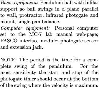
![$\textstyle\parbox{0.40\linewidth}{\hspace*{.1in}
\includegraphics[width=2.in]{f...
...nd bifilar support.
NOTE: $L$\space and $l$\space are equivalent.\end{center} }$](img143.gif)
SUGGESTED EXPERIMENTAL TECHNIQUE:
*.3in
Adjust the infrared gate height so that the bob interrupts the beam
at the bottom of the swing. (Make sure the PASCO interface is on and
that the phone jack is plugged into the first slot.)
To initiate the PASCO interface software click the
computer mouse when centered on the telescope icon in the ``toolkit'' area
below. There will be a just a single table for recording the measured period.
Start the pendulum swinging and
then
start the data acquisition by clicking the REC button button. Let the
bob swing for about
10 periods. Calculate the mean and standard deviation by simply
clicking on the table statistics icon (i.e.  ). For a single measurement of the period the
standard deviation is a reasonable measure of the uncertainty. With
10 measurements the uncertainty of the mean is better represented by
 . Can you explain this?
REQUIRED INVESTIGATIONS: (Error analysis required only for item
3)
*.3in
Period vs Amplitude: For a pendulum of convenient length L
(about 0.5 m) determine the dependence of period on angular amplitude.
(Do not cut string to decrease L; there are clips on the strings to adjust the length.)
Use
several amplitudes between 5 and 50 degrees. Measuring the angle is a bit hard; to avoid parallax effects, position your eye so the two strings are aligned with each other and read the protractor.
[Of course, the amplitude of the swing will decrease slowly because of friction. Keep the number of swings that you time small
enough that the amplitude changes (because of friction) by less than 5 degrees during the timing. This
is especially important for large amplitudes.] For each group of swings
timed, record the average angular amplitude.
*.3in
Plot the measured period as a function of angular amplitude including
a few error bars.
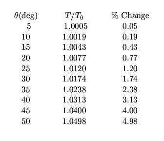
The accurate formula for period as a function of amplitude  is:
is:

where  and
and  is the angular amplitude.
The results follow:

![$\textstyle\parbox{0.40\linewidth}{\hspace*{.05in}
\includegraphics[width=1.8in]{figs/m07.eps}
}$](img149.gif)
Compare your plot (above) with values predicted from this table.
Period vs. Length: For an amplitude small enough that the period is
almost independent of amplitude, determine the variation of period with
length. (The length of the pendulum is the vertical distance from the
support to the center of the bob.) Try four or more lengths
from 0.20 m to 1.0 m.
Note: Change lengths by using the two spring-loaded clamps above
protractor.
I. Plot period (T) versus length (L) and extend the curve to L=0.
Can you tell at a glance how T0 depends on L?
II. Plot T02 vs L. What is the shape of this curve? What can you tell
from this curve about the dependence of T0 on L?
Measurement of g: With a pendulum about 1.0 m long, make a
measurement of g, the acceleration of gravity. (See your text for proof
that a simple pendulum swinging through a small angle has
 where T is the period, L the length and g is the acceleration of gravity.)
Take enough measurements to estimate the reliability of your period
determination.
*.3in
[4.]
Calculate the uncertainty in your determination of ``g''.
Note that  . (Take a look at the ``Errors and Uncertainties'' section of this manual.)
Is the accepted value within the limits you have set? If not,
can you explain it?
(Consider optional items below. The string lineal density is 0.5 g/m, and
 gms.)
gms.)
OPTIONAL EXERCISES:
*.3in
Show that the buoyant force of air increases the period to

where T0 is the period in vacuum and  is the density.
Test by swinging simultaneously two pendula
of equal length but with bobs of quite different densities:
aluminum, lead, and wooden pendulum balls are available. (Air resistance
will also increase T a comparable amount. See Birkhoff ``Hydrodynamics,''
p. 155.)
The finite mass of the string, m, decreases the period to

where M is the mass of the bob (S.T. Epstein
and M.G. Olsson, American Journal of Physics 45, 671, 1977). Correct
your value of ``g'' for the mass of the string.
*.3in
The finite size of a spherical bob with radius r increases the period
slightly. When L is the length from support to center of the sphere, then
the period becomes (see Tipler ``Physics'' 2nd ed. p. 346, problem 26):

What is the resulting percent error in your determination of ``g''?
NOTE:
For a comprehensive discussion of pendulum corrections needed for
an accurate measurement of g (e.g., to four significant figures) see
R. A. Nelson and M. G. Olsson, American Journal of Physiscs 54, 112,
(1986).


Next: MC-8 The Physical Pendulum
Up: PHYS 201/202 and 207/208
Previous: M-6 Uniform Circular Motion
Michael Winokur
4/7/2000
![]() ). For a single measurement of the period the
standard deviation is a reasonable measure of the uncertainty. With
10 measurements the uncertainty of the mean is better represented by
). For a single measurement of the period the
standard deviation is a reasonable measure of the uncertainty. With
10 measurements the uncertainty of the mean is better represented by
![]() . Can you explain this?
. Can you explain this?

![$\textstyle\parbox{0.40\linewidth}{\hspace*{.1in}
\includegraphics[width=2.in]{f...
...nd bifilar support.
NOTE: $L$\space and $l$\space are equivalent.\end{center} }$](img143.gif)


![$\textstyle\parbox{0.40\linewidth}{\hspace*{.05in}
\includegraphics[width=1.8in]{figs/m07.eps}
}$](img149.gif)

