next up previous contents
Next: MC-9  Angular Acceleration and Rotational Up: Mechanics Previous: MC-7  Simple Pendulum   Contents

MC-8  The Physical Pendulum

Do either PART A or PART B but not both!

PART A

OBJECTIVE:

To measure the rotational inertia of a ring by swinging it as a pendulum from a point of the rim and to compare the value to that computed.

APPARATUS:

Basic equipment: Metal rings, (full, half, and quarter rings); knife edge and 2-point supports.
Computer equipment: Personal computer set to the MC-8 lab manual web-page; PASCO interface module; photogate sensor and extension jack.

INTRODUCTION:

The period of a rigid body swinging on an axis as a pendulum is (for small amplitudes $\simeq 5 ^o$):

\begin{displaymath}T=2\pi\sqrt{\frac{I_{0}}{Mgh}} \end{displaymath}

where

\begin{eqnarray*}
T & = & \mbox{period} \\
I_0 & = & \mbox{rotational inertia...
...ity} \\
h & = & \mbox{distance from axis to center of mass.}
\end{eqnarray*}


REQUIRED INVESTIGATIONS:

  1. Initiate the PASCO interface software by clicking on the telescope icon. There will be just a single table for recording the measured period.

  2. Measure the period of the ring supported on the knife edge and swinging in its own plane. From the period calculate $I_0$. Use the parallel axis theorem to also calculate $I_c$, the rotational inertia about an axis through the c. of m. and perpendicular to plane of the ring. Compare this $I_c$ with the computed value of $I_c = M (r_1^2 + r_2^2)/2$ where the $r$'s are the inner and outer radii of the ring. Do the two $I_c$'s agree within reasonable experimental error? Explain.

  3. Measure the period of the ring when supported on the two sharp points but swinging perpendicular to its plane. From this period calculate the rotational inertia about an axis through those two points. Then use the parallel axis theorem to find the rotational inertia about a diameter of the ring. How does this rotational inertia compare with that about an axis perpendicular to the plane of the ring and through the center of mass?

    OPTIONAL PROBLEM: Prove that this relationship should exist by calculating the rotational inertias about the two orthogonal axes.

  4. One circular hoop has been cut in sections. Measure the period of a half-hoop when set at its midpoint on a knife edge; also the period of a quarter-hoop. (Be sure hoop sections have the same radius of curvature $r$).

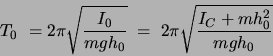
Proof that any section of a thin hoop has the same period if oscillating in the plane of the hoop:

Let
$r =$
radius of the thin hoop
$O =$
axis about which it swings (knife edge)
$C =$
center of mass of the partial hoop
$m =$
mass of the partial hoop
$h =$
$OC =$ distance from c. of m. to axis
Note that $ I_A= mr^2$ for any partial hoop.
The parallel axis theorem then gives:

\begin{displaymath}I_A = I_C + m(r - h)^2
\mbox{   or   } I_C = I_A - m(r - h)^2\end{displaymath}

\includegraphics[height=2.0in]{figs/m8-01.eps}

Hence

\begin{displaymath}I_C =  mr^2 - mr^2 + 2mrh - mh^2  =  2mrh - mh^2  . \end{displaymath}

When one substitutes this $I_C$ into

\begin{displaymath}T=2\pi \sqrt{I_0 /(mgh)}  =  2\pi \sqrt{(I_C+mh^2)/(mgh)} \end{displaymath}

one finds

\begin{displaymath}T = 2\pi \sqrt{(2mrh-mh^2+mh^2)/mgh}  = 2\pi \sqrt{2r/g} \end{displaymath}

or a period independent of what fraction of a hoop is used!

OPTIONAL PROBLEM:

For a thick hoop, the above relationship does not hold exactly. Show that the thickness of the laboratory hoops accounts for the small difference between $T$ for a whole hoop and $T$ for a half hoop. (This is a rather difficult problem. For the older style laboratory hoops the finite thickness increases the period by $\simeq$ 1.8%; the period of the half-hoop will be $\simeq$5.2% larger, and the quarter-hoop over 22% longer!)

PART B of M-8
KATER'S REVERSIBLE PENDULUM
OBJECTIVE: To study conjugate centers of oscillation and to measure g accurately.

APPARATUS:

Long rod with movable weights and knife edges; bearing surface (Kater's pendulum mount); infrared photogate & support stand; computer equipment as in PART A.

INTRODUCTION:

\includegraphics[width=1.2in]{figs/m8-02.eps}

When swung from O the period is:

\begin{displaymath}T_0 = 2\pi\sqrt{\frac{I_0}{mgh_0}}\; = \;
2\pi \sqrt{\frac{I_C + mh_0^2}{mgh_0}}\end{displaymath}

When swung from P:

\begin{displaymath}T_P =2\pi \sqrt{\frac{I_P}{mgh_P}}\; = 2\pi
\sqrt{\frac{I_C + mh_P^2}{mgh_P}} .\end{displaymath}

By substitution one easily verifies that $T_0 = T_P$ for two arrangements:


1) the trivial solution $h_0 = h_P$, and


2) when $I_C = mh_0h_P$.


For the second case:

\begin{displaymath}T_0 = T_P \; = \; 2\pi \sqrt{(h_0 + h_P)/g} \; =
\; 2\pi \sqrt{L/g}
\end{displaymath} (1)

where $O$ and $P$ are called conjugate centers of oscillation. (See note at end of experiment.) A measurement of the period ($T$) and distance ($L = h_0 + h_P$) between knife edges then gives an accurate value of $g$.

Empirically finding an $L$ to give $T_0 = T_P$ is tedious. Instead, find an $L$ for which $T_0 \sim T_P$ and then eliminate $I_C$ from the first two equations above to give:


\begin{displaymath}
\frac{4\pi^2}{g} \; = \; \frac{h_0 T_0^2 - h_P T_P^2}{h_0^2 ...
...T_P^2}{2(h_0 + h_P)} + \frac{T_0^2 - T_P^2}
{2(h_0 - h_P)}   . \end{displaymath} (2)

If one chooses an asymmetric geometry for the location of the weights, one can avoid $h_O \; \sim \; h_P$. Note then that for $T_0 \; \sim \;T_P$ the first term dominates, and an accurate value of $g$ results if one knows accurately $L = h_0 + h_P$, (the distance between the knife edges), and to much less accuracy the difference $ h_0 - h_P$.

SUGGESTED PROCEDURE:

  1. Find the approximate c. of m. of the pendulum plus asymmetrically located weights. Then set one knife edge as far from the c. of m. as feasible. This avoids $h_0 \sim h_P$ which would make the last term of Eqn. 2 large.
    NOTE: Keep this knife edge position fixed throughout the experiment.

  2. Determine the period of the pendulum, $T_0$, when swinging from this knife edge. Keep amplitude small ($< 5^{o}$) and use a photogate timer.
  3. Calculate the length, $L$, of a simple pendulum to give the same period.
  4. Set the second knife edge at this distance $L$ from the first knife edge.

  5. Determine the new period of the pendulum, $T_P$, for swinging from the second knife edge. This period $T_P$ will not quite equal $T_0$ since moving the second knife edge has changed slightly the c. of m. and hence $I_C,
\; h_0, \; h_P$, and also both $T_0$ and $T_P$.

  6. Recalculate the length $L$ of the equivalent simple pendulum to give this new period $T_P$. Then reset the knife edge accordingly.
  7. Redetermine the period about the first knife edge.
  8. One can continue this iterative process (6 thru 7) until the two periods are arbitrarily close to each other, and hence $g$ is given by Eqn. 1. However this is not necessary if one accurately finds the new c. of m. (e.g. by balancing the pendulum on the knife edge for the hoops of M-8A) and then uses Eqn. 2.

  9. Estimate your uncertainty in g and compare with accepted value (see M-4).


NOTE: These two conjugate centers of oscillation ($O$ and $P$) exist of course for any rigid physical pendulum, e.g. a baseball bat:

Let one center of oscillation be where the batter grasps the bat. The conjugate center of oscillation is then called the center of percussion because if the ball hits the bat at this point, the blow rotates the bat about the other center of oscillation, (i.e. the batter's hands) and so the bat transmits no ``sting" to the hands. However, if the ball hits very far from the center of percussion, the hands receive much of the blow and an unpleasant ``sting'' can result.


next up previous contents
Next: MC-9  Angular Acceleration and Rotational Up: Mechanics Previous: MC-7  Simple Pendulum   Contents
Physics Laboratory 2001-08-29