


Next: EC-7 Magnetism
Up: Electricity and Magnetism
Previous: EC-3 Capacitors and RC-decay
Contents
OBJECTIVES:
- To observe magnetic deflection of electrons, at fixed
energy, in a uniform magnetic field and then use this information to obtain
e/m, the electron charge/mass ratio.
APPARATUS:
-
Figure 1:
Foreground: dip-needle magnetic-field sensor sitting on power supplies with built-in
digital meters; Background: Sargent-Welch e/m equipment and black cardboard.
|
Figure 1
![\includegraphics[height=3in]{figs/e6-01.eps}](img73.png)
|
INTRODUCTION
- Your e/m vacuum tube contains a number of features for producing and visualizing a
thin uniform electron beam. Refer to Figs. 2 & 3 for schematic detais. Passing current
through a wire filament (F) causes it to become hot and if the hot filament is in close
proximity to a higher
potential electrical element (the anode C) some of the electrons will accelerate through the
vacuum towards the anode. To allow a narrow beam of electron to leave the
vacinity of the anode a thin slit, S, has been cut in the anode cylinder.
Normally the electron beam is invisible to your eye. However the e/m tube also contains a
saturated vapor pressure of Hg. When electrons, with energies in excess of 10.4 eV collide with
Hg atoms, some atoms become ionized and some become excited. (These electrons are, of course,
now permenently lost from the beam). Most of the Hg atoms/ions quickly recombine and/or de-excite to
emit a bluish light before moving appreciably from the collision center. Hence the bluish
light marks the path taken by the electron beam.
The potential difference  between the filament and
anode (Fig. 2 and 3)
accelerates electrons thermionically emitted by the filament. Those
electrons travelling toward the slit S emerge with a velocity
between the filament and
anode (Fig. 2 and 3)
accelerates electrons thermionically emitted by the filament. Those
electrons travelling toward the slit S emerge with a velocity  given by
 |
(1) |
provided that the thermal energy at emission is small compared to
 .
.
Preliminary Questions:
- 1. What is purpose of the Helmholtz coil (read through the appropriate section first)?
- 2. What aspect of the electron trajectory will indicate that it is undergoing uniform
circular motion?
Figure 2: The e/m tube viewed along the earth's magnetic field (i.e.,

is perpendicular to the page).
![\includegraphics[width=4.8in]{figs/e6-02.eps}](img78.png)
Figure 3: Side view of Figure 2.
![\includegraphics[width=4.8in]{figs/e6-03.eps}](img79.png)
- If the tube is properly oriented, the velocity of the emerging electrons is
perpendicular to the magnetic field. Hence the magnetic force vector
 ,
which is described as a cross product
,
which is described as a cross product
 ,
supplies the centripetal force
,
supplies the centripetal force
 for a circular path of radius
  .
Since
.
Since  is perpendicular to
 |
(2) |
Eliminating between (1) and (2) gives
 |
(3) |
Our digital voltmeter measures accurately the accelerating voltage
. The
radius of curvature, or  , is half the distance between the filament
  and one
of the cross bars attached to rod
and one
of the cross bars attached to rod  . The cross bar positions are as follows:
| Crossbar No. |
Distance to Filament |
Radius of Beam Path |
| 1 |
0.065 meter |
0.0325 m |
| 2 |
0.078 meter |
0.039 m |
| 3 |
0.090 meter |
0.045 m |
| 4 |
0.103 meter |
0.0515 m |
| 5 |
0.115 meter |
0.0575 m |
To find  we still need to know the magnetic field strength
  . Instead
of measuring , we calculate it from the dimensions of the Helmholtz
coils and the measured coil current,
. Instead
of measuring , we calculate it from the dimensions of the Helmholtz
coils and the measured coil current,  , needed to bend the beam so that it hits a
given cross bar.
, needed to bend the beam so that it hits a
given cross bar.
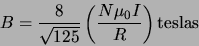
The field at  is in fact:
2
is in fact:
2
 |
(4) |
as one easily sees by adding the axial fields  from each of the
single coils:
from each of the
single coils:
Thus when X = R/2, then
In Eqn. 4,

- number of turns on each coil (72 for these coils)

- current through each coil in amperes

- mean radius of the coils in meters (approximately
0.33 m but varies slightly from unit to unit)

-
 tesla meter/ampere.
Finally if we substitute (4) into (3) we obtain
 |
(5) |
CIRCUIT DIAGRAM: Fig. 5 should help you hook up the
components. The current must have the same direction in both sets of Helmholtz coils.
Figure 5:
Basic wiring layout.
|
|
SUGGESTIONED PROCEDURE:
- 1.
- Set the axis of the Helmholtz coils along the local direction of
the earth's field,
 , as determined with a compass and dip needle.
The axis should point towards the geographic north but at an angle about 60 degrees
from the horizontal. Thus the axis should point deep under Canada.
Put the long axis of the e/m tube in the north-south direction and with the cross bars
up.
, as determined with a compass and dip needle.
The axis should point towards the geographic north but at an angle about 60 degrees
from the horizontal. Thus the axis should point deep under Canada.
Put the long axis of the e/m tube in the north-south direction and with the cross bars
up.

| CAUTION: Nearby ferromagnetic material (e.g. steel in the power supply, the table
and in the walls) can alter
the local direction of .
As long as the field
direction does not change during the experiment, there should be no
problem. |
- 2.
- Set the filament supply knob to zero before turning the power on.
A red light comes on when excessive filament current or a too rapid
increase trips a protective relay.
Reset by putting the filament control to zero and slowly turning it up.
- 3.
- Since depends on
 , one needs high quality meters for
and .
Our digital meters have an accuracy of
, one needs high quality meters for
and .
Our digital meters have an accuracy of  one digit in the last displayed
digit.
one digit in the last displayed
digit.
- 4.
- Start with
 between filament and
anode. With the room dark, gradually turn up the filament control
until the beam is visible. To make the beam more visible use
black cloth and black cardboard to block out stray light:
place the black cardboard inside the Helmholtz coils and view from
the top. If the protection circuit trips and a red light comes on,
reset by zeroing the filament control; then turn it up
slowly. When the beam appears, adjust the
filament control to give 5-10 mA of anode current. Do not exceed
15 mA! With no current through the Helmholtz coils,
the earth's magnetic field
should slightly curve the beam (like the dotted line in Fig. 2.)
between filament and
anode. With the room dark, gradually turn up the filament control
until the beam is visible. To make the beam more visible use
black cloth and black cardboard to block out stray light:
place the black cardboard inside the Helmholtz coils and view from
the top. If the protection circuit trips and a red light comes on,
reset by zeroing the filament control; then turn it up
slowly. When the beam appears, adjust the
filament control to give 5-10 mA of anode current. Do not exceed
15 mA! With no current through the Helmholtz coils,
the earth's magnetic field
should slightly curve the beam (like the dotted line in Fig. 2.)
- 5.
- Correction for the earth's magnetic field:
Increase through the Helmholtz coils
until the beam deflects. If the sense of deflection
is the same as that from the
earth's field (i.e. when
 ), reverse the leads to the Helmholtz coils;
the curvature should then be like
B in Fig. 2. The field from the coils then opposes the
earth's field; hence adjust the coil current until the beam
path is straight. Since light travels in straight lines, the beam
should then hit the glass at the center of the area illuminated by light
from the filament.
), reverse the leads to the Helmholtz coils;
the curvature should then be like
B in Fig. 2. The field from the coils then opposes the
earth's field; hence adjust the coil current until the beam
path is straight. Since light travels in straight lines, the beam
should then hit the glass at the center of the area illuminated by light
from the filament.
- This field current which just cancels the earth's field, we will call
 .
Clearly the for Eqn. 5 must have subtracted: Let the correct
field current for crossbar
.
Clearly the for Eqn. 5 must have subtracted: Let the correct
field current for crossbar  be
be  , and let
  be the measured
current to bend the beam around so that the outside sharp edge of the beam hits
the center of the
be the measured
current to bend the beam around so that the outside sharp edge of the beam hits
the center of the  crossbar. Hence
 - I
- I is the correct
current to bend the beam to the appropriate radius,
is the correct
current to bend the beam to the appropriate radius,  .
.
MORE ACCURATE METHODS TO ELIMINATE THE EFFECT
OF THE EARTH'S FIELD:
- Uncertainty in can dominate the uncertainty in
, so consider using the following more accurate methods to
eliminate the effect of the earth's field:
- i.
- Take two readings of coil
currents at
 ,
,  and
and  : one with the earth's
field opposing that
of the Helmholtz coils, the other with it aiding. To
accomplish this, first (with the cross bars up) measure (as described
above); then rotate just the e/m tube 180
: one with the earth's
field opposing that
of the Helmholtz coils, the other with it aiding. To
accomplish this, first (with the cross bars up) measure (as described
above); then rotate just the e/m tube 180 about its long axis.
| CAUTION:
Always rotate the tube in the sense to REDUCE the TWIST in the
filament and anode leads.
Otherwise one can twist the leads off. |
Next
reverse the current in
the Helmholtz coil and adjust it so that the beam again hits the same cross
bar. Call this reading . Then
- ii.
- Or better yet, for each cross bar record an and
 reading. The
average
reading. The
average
is the current required if the earth's field were absent. You may find it easier to
measure  for
for  to 5 and then rotate the e/m tube just once to measure
  .
.
MEASUREMENTS AND ANALYSIS: (If time is short, measure only two cross bars
at each voltage.)
- Make two determinations of for each cross bar.
- Repeat for an
accelerating voltage of
 44 volts. (Note should remain the same and
one can measure it more precisely at the lower accelerating voltage.)
44 volts. (Note should remain the same and
one can measure it more precisely at the lower accelerating voltage.)
SUGGESTED DATA TABULATION: {If you use the alternative method
(ii. above),
replace by and
 by
by
 ).}
).}
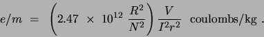
- Estimate the reliability of your value of and compare to
 C/kg.
C/kg.
OPTIONAL:
- Note that the electron beam
expands in a fan shape after leaving the slit.
Interchange the filament leads and note how the fan shape flips to the
other side of the beam.
- Explanation: The fan shape deflection arises
from the filament current's magnetic
field acting on the beam. Our filament supply purposely uses unfiltered
half wave rectification of 60 Hz AC so that for half of the cycle
no current flows thru
the filament but which is still hot enough to emit sufficient electrons. The
electrons emitted in this half cycle constitute the sharp beam edge
which we use for
measurement purposes. This trick not only avoids deflection effects for
this part of the beam, but also avoids the uncertainty in electron energy
arising from electrons being emitted from points of different
potential along the filament. (During this half cycle of no filament current
the filament is an equipotential.) The fan shape deflection
relates to electrons emitted during the other half cycle when filament
current flows.
[See: F.C. Peterson, Am. J. Phys. 51, 320, (1983)]
Next: EC-7 Magnetism
Up: Electricity and Magnetism
Previous: EC-3 Capacitors and RC-decay
Contents
Physics Laboratory
2001-08-28
![\includegraphics[height=1.5in]{figs/e6-04.eps}](img96.png)
![\begin{displaymath}B(X) = \frac{N\mu _0IR^2}{2\left[ R^2 + X^2\right] ^{3/2}}.\end{displaymath}](img100.png)
![\begin{displaymath}B = 2B(X) = \frac{N\mu _0I^2R^2}{\left[ R^2 + R^2/4\right] ^{...
...{3/2}} = \frac{8}{\sqrt{125}}
\left(\frac{N\mu _0I}{R}\right) .\end{displaymath}](img101.png)
![\includegraphics[width=6.0in]{figs/e6-05.eps}](img109.png)