


Next: M-2 Equilibrium of Forces
Up: MC-1 Errors & Motion
Previous: MC-1b Errors and the Density
Contents
OBJECTIVES:
- The major objectives of this exploratory computer lab are two-fold. Since
you will be using computer based data-acquisition throughout this course,
we expect
you to become familiar with the
PASCO© (page
![[*]](http://badger.physics.wisc.edu/icons/latex2html/crossref.png) ) interface hardware and software.
Our second objective is for you to develop an intuition for
Newtonian mechanics by experimenting
with 1-D motion. There is no extensive write-up in
this lab, but only a series of recommended experiments and the requirement
to write down your observations in your lab book/form.
) interface hardware and software.
Our second objective is for you to develop an intuition for
Newtonian mechanics by experimenting
with 1-D motion. There is no extensive write-up in
this lab, but only a series of recommended experiments and the requirement
to write down your observations in your lab book/form.
THEORY:
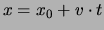
- The motion of an object is described by
indicating its distances
 and
and  from a fixed reference point at two
different times
from a fixed reference point at two
different times  and
and  . From the change in position between these two
times one calculates the average velocity (remember that direction is implied)
for the time interval:
. From the change in position between these two
times one calculates the average velocity (remember that direction is implied)
for the time interval:
The acceleration of an object is found
by finding its velocity  and
and  at two different times and .
From the change in velocity between two different times one calculates the
average acceleration for the time interval:
at two different times and .
From the change in velocity between two different times one calculates the
average acceleration for the time interval:
FUNDAMENTAL CONCEPTS:
- The equation that
describes the motion of an object that
moves with constant velocity is:
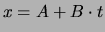 .
.
If you make a plot of  versus
  , you find that it describes a
straight line.
The letter
, you find that it describes a
straight line.
The letter  indicates the position of the object at time
  .
The letter
.
The letter  is the slope of the line, and is equal to the velocity of the
object. So we can rewrite this
is the slope of the line, and is equal to the velocity of the
object. So we can rewrite this
 .
.
- The equation that describes the motion of an object that
moves with constant acceleration is:
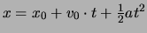 and
and  .
.
So we can rewrite this as:
 and
and 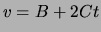 .
The letter indicates the position of the object at time .
The letter is the
the velocity of the
object at time , and is the slope of the graph at this time.
The letter C is equal to half the acceleration.
.
The letter indicates the position of the object at time .
The letter is the
the velocity of the
object at time , and is the slope of the graph at this time.
The letter C is equal to half the acceleration.
PRECAUTIONS:
- In order for the position sensor to work properly it must be pointed in such a
way that it ``sees'' the vane, and doesn't identify the front of the cart; that
means that it must be pointed slightly upwards. The sonic ranger tends to
``see'' the closest reflecting surface. In addition the minimum range is
approximately 40
 .
.
Make sure you do not drop the carts or allow them
to roll off the table, because it damages the bearings and they begin to
suffer too much friction. Try to arrange to keep the cart on the track all the time.
APPARATUS

- Computer with monitor, keyboard and
mouse.
- A PASCO position sensor;
this device emits a series of short pulses of sound, and receives
the echo of the
sound reflected by a nearby object. The length of the
time interval between the emission
and the reception of the sound pulse depends on the distance to the reflecting
object.
This method of locating an object is the same as the one used by bats to find
flying insects or by navy ships to locate submarines.
- A PASCO Signal Interface converts the time interval
between the emission and reception of the sound pulse to digital form
, i.e., numbers that can be then plotted on the monitor.
- PASCO dynamic track with magnetic bumpers; cart with reflecting vane;
meter stick; one or two steel blocks.
PROCEDURE:
- Your instructor will demonstrate how to configure the experiment.
To initiate the PASCO(page ) interface software you will
need to click the computer mouse on the telescope icon in the
``toolkit'' area below. The Fig. 1 below shows how the
display should appear. Note that, while you are able to reconfigure the display
parameters, the default values that are specified on start-up will allow you to
do this experiment without necessitating any changes. All three measured
quantities,
position, velocity, and accelation, are displayed simultaneously. Since velocity
is determined from the position data and acceleration from the velocity the ``scatter''
in the data will become progressively more pronounced.
Figure 1:
The PASCO scientic workshop display format
|
|
Experiment I, Basic Operation and Sonic ranger calibration:
- To start the data acquisition CLICK on the REC icon. To stop it CLICK on the
STOP icon (the upper left window is configured like a tape player). Each run gets
its own data set in the ``Data'' display window. If there are any data sets in existence
you will not be able to reconfigure the interface parameters or sensor
inputs, unless you clear (delete) all data.
- With the REC option on move the cart to and fro and watch
the position, velocity and acceleration displays.
- STOP the data acquisition.
- CLICK once (or twice) on the AUTOSCALE icon. CLICK on the MAGNIFY icon and
move to one of graph regions and CLICK again. CLICK on the CROSSHAIR icon and move
about on the various graphs. Change the plot display region be manual adjusting the
-min, -max, etc. values. To do this CLICK in the various scale
(time, position,etc.) areas.
CLICK on the STATISTICS icon once and then again. Make sure that
all three members of the team have an opportunity to test these components.
It is imperative that
the basic operations on the software interface are understood by everyone!
- DELETE the data set by a CLICK on the RUN #1 item in the ``Data'' window and then
striking the ``Delete'' (
 DEL
DEL ) key.
- Start the data acquisition and observe the closest distance to the sonic ranger at
which it still functions. This value is supposed to be close to 40 . If
it is much larger, re-aim the position sensor.
- Configure the distances so that when the cart nearly touches the near magnetic bumper
the sonic ranger still records accurately.
- Measure the position at two distances approximately 1
 apart and compare the
printed centimeter scale with the position sensor readout. By how much do the
readings differ?
apart and compare the
printed centimeter scale with the position sensor readout. By how much do the
readings differ?
Experiment II, Inclined Plane and Motion:
- Raise the side of the track furthest from the position sensor using one
of the supplied blocks. Hang the 500
 weight off the other side to weigh the
front end down and prevent unwanted slippage of the track (See the demonstration
set-up to see how the weight should be positioned.)
weight off the other side to weigh the
front end down and prevent unwanted slippage of the track (See the demonstration
set-up to see how the weight should be positioned.)
- Find an appropriate release point that allows the cart to roll down the
track without striking the magnetic bumper.
- CLICK the REC button and release the cart letting it bounce three or four
times and the CLICK the STOP button.
- Qualitatively describe the shape of the three curves: position, velocity
and accelation and discuss how they evolve with time.
- Obtain a hard copy of this data by simultaneously pressing the Alt-p
keys.(Only one copy is made even if you ask for more.) Repeat this step to get additional
copies.
- Label/identify the various key features in the various curves by
writing directly on the hard copies. Paste the graphs in your note bood.
QUESTIONS: (to be discussed as a group)
- Does the velocity increase or decrease linearly with time when it is sliding
up or down the track?
- When the velocity is close to zero can you observe any discrepancies in the
data? Can you think of a reason for any deviations from linearity?
- Why does the maximum of the position readout fall with each subsequent bounce?
- Is the collision with the magnetic bumper or the residual friction in the
bearing the most likely source of loss?
- Can you think of a method using your data to determine which of these two proposed
mechanisms is the most likely culprit?
Experiment III, Reproducing Expt. II manually:
- Remove the block so that the cart is no longer raised.
- Start a new data set (by clicking the REC button) and try to move
the cart back and forth at constant velocity using your hand from the
side. Alternatively have one team member aim the position sensor at
another member holding a book waist-high and walk towards the sensor
or away from the sensor.
- Using the cross hair estimate your velocity in
either
 or
or  .
.
- Repeat step 3. but now try to obtain a region of constant accelation.
Experiment IV, Accelation at (9.8  ):
):
- Have one member of the group stand carefully on a chair and hold
the position sensor facing downward above another member's head while he or
she is holding a notebook on their head.
- Start a new data set and have the student holding the notebook jump up
and down a few times.
- Stop the recording and determine whether free-fall yields a constant
accelation close to the accepted value.
- You may wish to try the statistical analysis module to measure your
acceleration. Ask you lab instructor for a demonstration.
- Fini.
Next: M-2 Equilibrium of Forces
Up: MC-1 Errors & Motion
Previous: MC-1b Errors and the Density
Contents
Physics Laboratory
2001-08-29
![\includegraphics[width=4.0in]{figs/motion0.eps}](img131.png)