


Next: MC-14-Elastic and Inelastic Collisions
Up: Mechanics
Previous: M-12 Torsion Pendulum and Shear
Contents
OBJECTIVE:
- To study gyroscopes and to check the
relationship between angular momentum, applied torque and rate of
precession.
REFERENCES:
- Don't do this experiment before reading about
angular momentum and gyroscopes; see also the Mitac
Instruction Manual, especially pages 1-7, experiments 1-4, pages
11-14, and Sec. 6 on ``Operation''.
APPARATUS: Mitac Gyroscope, 150 g and 300 g snap on
slotted masses, and stroboscope.
SUGGESTIONS:
- Read the sections of the Mitac Manual referred to
above, start the gyroscope, and experiment with it. For example, predict the
direction of precession when a certain torque is applied; then check it
experimentally.
- When you have become familiar with the operation of the
gyroscope perform
the following quantitative experiment:
- i.
- Calculate the rotor's angular momentum from the following data:
|
Outer diameter of rotor | 20.0 | cm |
|
Inner diameter of rotor | 15.1 | cm |
|
Thickness of rotor | 2.54 | cm |
|
Rotor webb thickness | 0.435 | cm |
|
Hub diameter | 3.01 | cm |
|
Mass of rotor | 2.73 | kg |
|
Rotor rpm | 150 | |
|
(Check rotor rpm with the stroboscope) |
- ii.
- Place one of the supplied weights into the groove on the rotor axis
so as to create a torque on the axis and cause the gyroscope to precess.
From this weight and its position, calculate the torque.
Predict the rate of
precession by using the calculated torque and angular momentum.
Check by experiment.
- iii.
- Ask your instructor what other quantitative measurement you should make.
The experiments in the Mitac Manual are good possibilities.
Alternative M-13 Gyroscope:
OBJECTIVE: To study gyroscopic effects especially precession and nutation.
APPARATUS: Air bearing gyroscope, torque weights, timer, stroboscope.
INTRODUCTION: Review gyroscope treatment in text (or in
handout).
|
CAUTION:
The air bearing surfaces and torque
shaft can easily suffer
damage so handle carefully: e.g. when the air pressure is on (and ball
friction negligible) the glued-on torque shaft may break off if
the shaft bangs against the stationary ball holder.
|
![\includegraphics[height=3.3in]{figs/m13-01.eps}](img417.png)
|
SUGGESTED STUDIES:
- Qualitative explorations: With air flow on to minimize friction,
spin ball by twisting the torque shaft with thumb and forefinger. Observe
precession about the vertical
 axis, and observe nutation
(torque shaft
bobbing
up and down) for different torque weights on the shaft and for different
spin angular velocities,
axis, and observe nutation
(torque shaft
bobbing
up and down) for different torque weights on the shaft and for different
spin angular velocities,  . Upon what factors does the precession
depend?
. Upon what factors does the precession
depend?
Observe the three basic nutation patterns when the total torque
weight,  , has:
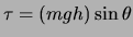
a) no initial vertical velocity:
| |
|
![\includegraphics[height=0.6in]{figs/m13-02.eps}](img420.png)
|
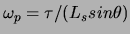
b) a small initial vertical velocity:
| |
|
![\includegraphics[height=0.6in]{figs/m13-03.eps}](img421.png)
|
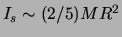
c) an initial small horizontal velocity:
| |
|
![\includegraphics[height=0.6in]{figs/m13-04.eps}](img422.png)
|
- Measure the angular acceleration,
 , from the air friction: For
low use a stopwatch and time the revolutions of a mark on the
rotating shaft. Plot spin angular velocity, , versus time (remember to
plot average at the middle of the time interval).
Calculate from
the slope. For higher use the stroboscope. To avoid errors from
subharmonics synchronizing with the mark on the shaft, start with the strobe
at too high a frequency. If the synchronization is at the n
, from the air friction: For
low use a stopwatch and time the revolutions of a mark on the
rotating shaft. Plot spin angular velocity, , versus time (remember to
plot average at the middle of the time interval).
Calculate from
the slope. For higher use the stroboscope. To avoid errors from
subharmonics synchronizing with the mark on the shaft, start with the strobe
at too high a frequency. If the synchronization is at the n higher
harmonic, you will see the shaft marks appear at
higher
harmonic, you will see the shaft marks appear at  different places.
- Calculate mass of the unweighted torque shaft from observed precessional
angular velocity,
 .
Spin the shaft at about
.
Spin the shaft at about
 rad/s and minimize nutation by starting
the shaft with a small horizontal (or slightly upward) velocity to
approximate the expected. Since the torque
rad/s and minimize nutation by starting
the shaft with a small horizontal (or slightly upward) velocity to
approximate the expected. Since the torque
 and
and
 , we predict is independent of
 .
Check this experimentally.
With spin angular momentum
.
Check this experimentally.
With spin angular momentum
 the result is
For the shaft mass  of the ball,
 where
where  is
radius of the ball. Measure the appropriate quantities and calculate .
Compare with and
is
radius of the ball. Measure the appropriate quantities and calculate .
Compare with and  measured directly for an unattached torque shaft.
- Sleeping Top: If
then one can show (see handout) that the gyroscope will spin
without nutation if released carefully
at = 0. You can observe the qualitative effect by starting with a
higher and then gradually slowing down
by touching the rotating
ball symmetrically in the horizontal plane until becomes critical
when the shaft will suddenly fall out of the vertical line. Calculate and
check this critical .
OPTIONAL:
- Nutation frequency,
 : One can show (see handout) that:
Check this expression when
rad/s. If one has time, change
m and h by adding torque weights and check the new ratio of
 .
.
Amplitude of nutation: The handout shows that the
amplitude of nutation varies as 1/L . Since
,
spinning the
gyroscope faster should reduce nutation amplitude at the same time the
nutation frequency increases. Check this at least qualitatively.
Use strobe to measure high .
. Since
,
spinning the
gyroscope faster should reduce nutation amplitude at the same time the
nutation frequency increases. Check this at least qualitatively.
Use strobe to measure high .
Next: MC-14-Elastic and Inelastic Collisions
Up: Mechanics
Previous: M-12 Torsion Pendulum and Shear
Contents
Physics Laboratory
2001-08-29
